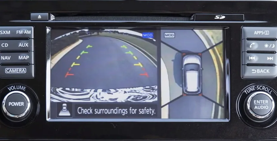
Nissan Around View Monitor combines an overhead composite with a conventional rear view. Source: Nissan News press material
How a car creates a 360-degree bird's-eye view
The camera that appears to be hovering several metres above a car does not exist. A typical 360-degree parking system captures the ground with four ultra-wide cameras mounted at the front, rear and beneath the door mirrors. An electronic control unit then reshapes those low viewpoints and combines them into one virtual overhead image.
The display is convincing because road markings and kerbs are close to the flat surface used by the calculation. It is not a literal aerial photograph. Tall objects can lean, stretch or break at the seams, while a graphic model of the vehicle normally covers the central area that the exterior cameras cannot see from above.
Four overlapping views
Bosch describes a layout with a forward-facing camera, a rear-facing one and two side cameras integrated into the mirrors. Its near-range cameras have a 190-degree aperture, giving adjacent cameras overlapping fields of view. Texas Instruments documents systems with four to six fisheye cameras, but four remains the familiar passenger-car arrangement.
The front unit is commonly placed in the grille or bumper, while the rear unit sits near the tailgate handle or registration plate. Position matters as much as resolution. The processor must know each camera's height, angle, lens distortion and position relative to the vehicle.
Some systems also use ultrasonic parking sensors. They can supply measured distance to a nearby obstacle, support warnings or contribute to low-speed braking. They do not produce the pixels used to show the ground; the video texture comes from the cameras.
Removing the fisheye curve
The wide lens captures the area close to the body but bends straight lines in the raw frame. Texas Instruments identifies lens-distortion correction as the first part of geometric alignment. Software applies an inverse model of the lens distortion so that a curved parking stripe becomes usable geometry.
The next operation is a perspective transformation. Each corrected image was recorded by a camera looking outward and down, yet the final display must look vertically downward. A transformation matrix remaps pixels from each camera onto a common ground plane.
Manufacturing calibration can use marked panels arranged around the car. Adjacent cameras see the same reference features, allowing the software to solve their relative positions and find the transformation that best aligns the points. The resulting lookup tables can then be stored and applied rapidly to every new video frame.
Hiding the joins
Once the four views share the same virtual perspective, their overlapping regions still need to become one image. The composite algorithm selects and blends information from neighbouring cameras so that the boundary is less distracting.
Brightness and colour require a separate correction. A left camera facing shade and a right camera facing direct sunlight may render the same white line differently. Texas Instruments calls the solution photometric alignment: exposure, colour and white-balance differences are reduced before the pixels are blended.
The car in the middle is generally a rendered model matched to the body shape and colour. Bosch's 3D system uses an animated vehicle model, while its camera imagery is projected around that model. This is why the roof can look perfectly clean even when no exterior camera has a position from which to photograph it.
Why bollards can look bent
A basic two-dimensional system assumes the world around the car is a flat surface. That works well for paint, paving and the point where a tyre meets the road. A bollard or pedestrian rises above that plane, so pixels from the top are projected to the wrong apparent location. The object may seem to lean away from the car.
The transitions between cameras create another weak point. A Nissan owner's manual warns that a tall object near a seam may not appear completely in the bird's-eye display. Volvo similarly identifies blind sectors at the joints and says an obstacle can remain hidden until it is close.
Modern three-dimensional systems change the projection surface rather than eliminating the source limitation. The Texas Instruments design maps near areas onto a flat base and more distant areas onto the raised sides of a bowl. Bosch describes a dynamic 3D wireframe adjusted using the environment model. These approaches render upright objects more naturally and enable rotatable viewpoints, but they still depend on cameras mounted close to the ground.
Calibration matters after repairs
The transformation remains accurate only while a camera sits where its stored parameters expect it. A folded mirror, an open door or tailgate, or damage that changes a mounting angle can disrupt the composite. A repaired mirror housing, grille, bumper or tailgate may therefore require the manufacturer's calibration procedure.
A useful check on a used car is to stop on level ground with straight bay markings. Lines should continue reasonably across the stitched boundaries. A large step, doubled object, rotated sector or black panel deserves investigation. It may be caused by dirt or a folded mirror, but it can also point to poor installation or missing calibration.
Lens condition matters too. Mud, water droplets, snow and ice obscure a much larger real-world area than their size on the lens suggests. Strong glare, darkness and large exposure differences can reduce detail even when the processor is working correctly.
A parking aid, not a measurement instrument
The display helps a driver place wheels, avoid a kerb and understand the car's footprint at low speed. It should not be treated as a perfectly scaled map. Apparent distances can differ from reality, and the seam zones can hide narrow or tall hazards. Mirrors, direct observation and parking sensors still have a role.
Nissan announced Around View Monitor for the Japanese Elgrand in 2007 as a production application built from four cameras. The central idea remains the same nearly two decades later. What has advanced is image resolution, processing speed, 3D projection and object detection. The apparent drone view is still created by four practical steps: correct the lens, transform the perspective, match the images and stitch them in real time.